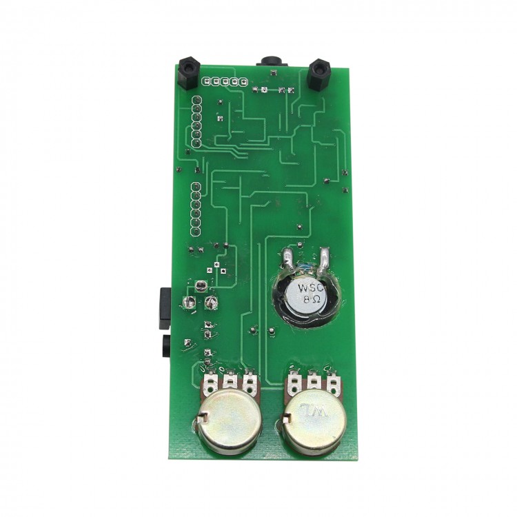

Pin 2 receives serial clock timing pulses from the Arduino to control the timing of the incoming data. The value of the resistance is controlled by serial input data from the Arduino applied to pin 3.

It provides a variable resistance across pins 5, 6 and 7 simulating a normal 3 terminal variable resistor or potentiometer.

D1 switches on whenever pin 8 switches low giving a visual representation of the incoming Morse code.
MORSE CODE AUDIO DECODER SERIES
Hence the LM567 is able to turn a correctly tuned Morse code tone at the input into a series of logic 0s and 1s at the output. The output pin 8 normally floats to a logic high due to its output load R1/D1, however if the audio tone at the input matches the frequency of the VCO, the output pin 8 switches low. Audio tones from the receiver are fed into pin 3. Using the component values provided, the bandwidth and frequency range is selective enough that you can select one of several stations that are transmitting close together just by tuning that station to the correct tone. Capacitors C1 & C2 form a filter with the bandwidth set by the value of C1. The VCO frequency is set by capacitor (C4) and a variable resistor placed across pins 5 & 6. The LM567 is a tone decoder with its centre frequency controlled by a voltage controlled oscillator (VCO). The circuit consists of an LM567 tone decoder, an MPC41010 digital potentiometer, an Arduino Nano and an LCD. If you prefer or have one on hand, you can use an Arduino Uno if you wish, its just bigger and will require a larger case.Īs indicated earlier, I have integrated WB7FHC’s audio filtering circuit with an Arduino Nano.
MORSE CODE AUDIO DECODER SOFTWARE
You are of course welcome to try and use Budd’s sketch in this project, you may prefer the operation of his decoder software to mine.Īs with several of my projects, I am using the Arduino Nano for this project due to its conveniently small size. In fact Budd’s software sketch will work just fine with my circuit although it will operate a little differently to mine. For my project I’ve integrated WB7FHC’s audio filtering circuit with a standard Arduino Nano and modified his software for my own feature preferences. The unit automatically adjusts itself to the speed of the incoming Morse code and displays the speed on the LCD.īudd’s original open source project doesn’t actually use an Arduino module as such, instead he incorporates the Arduino’s processor chip and clock components directly onto a ready-made decoder PCB. All functions are controlled by three push buttons along the top of the unit. It includes a software controlled noise impulse filter, an automatic input-frequency tuning circuit and a switchable Farnsworth setting for receiving Morse that uses Farnsworth timing. The decoder will receive Morse code from an audio source, decode it and display it on a built-in 4 line, 20 character LCD. The VK2IDL Morse Decoder is based on an excellent open source design by Budd Churchward, WB7FHC. And so, the idea of building my own Morse decoder was born. In the process I was curious to note that there were a number of hardware and software Morse decoder units available, although reports on their performance varied. I started looking for on-line Morse training websites in the hope of recovering some of my proficiency. I had studied Morse Code back in the 1980’s as a requirement for my advanced AOCP and used it regularly enough to maintain a reasonable proficiency for a number of years.

The idea of building a Morse decoder is the result of having recently returned to amateur radio after a long absence. VK2IDL Morse Decoder displaying live Morse from the VK2WI automated Morse practice transmission on 3.699 MHz.


 0 kommentar(er)
